General Guidelines
Wall Thickness
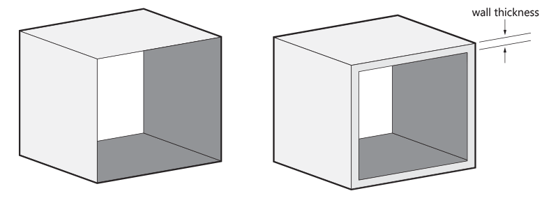
In 3D printing, wall thickness refers to the distance between one surface of your model and the opposite sheer surface. As your model is created in multiple steps, most wall thickness requirements of your design will be related to the ‘green state’ of your model. After printing, your model is cured in an oven. The extra powder that was not bound, and is not part of your design, is then removed. At this point, your model is still very fragile. This stage, which we call the “green state”, requires your model to be structurally sound. The green state affects wall thickness, overhangs, inside edges and knife edges. The infusion process affects transitions and connections.
Minimum Wall thickness
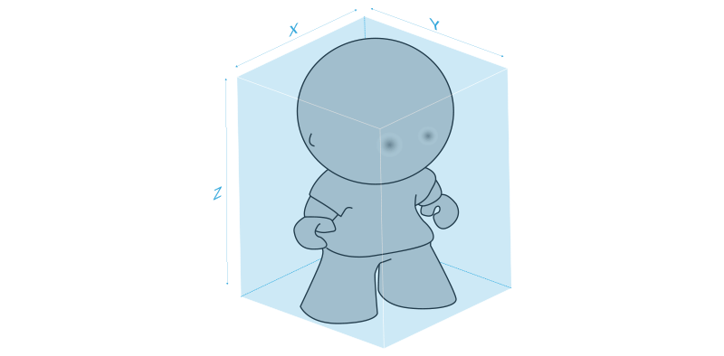
Different sized models require different minimum wall thicknesses because of the green state. Minimum wall thickness increases if the overall size of your model increases. You can consult the chart with the minimum requirements for walls with different ranges of X, Y or Z dimensions. You will see that small models, such as rings, can have a minimum wall thickness of 1 mm if they are well supported. Medium-size objects can have walls between 1.5 mm and 2 mm. For larger models, we highly recommend a wall thickness of 3 mm.
Overhangs
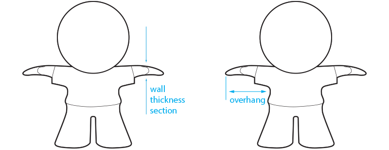
It is important to note that even with a 3 mm wall thickness, your model should not have any overhangs or “limbs” sticking out that could collapse under their own weight. These unsupported elements should be at least 6 mm all around. Unsupported overhang parts over 25 mm will not be accepted.
For example, large, bulky geometries connected to thin structures (such as a large head on a slim neck), could break while the model is being handled before infusion. Your model must be designed to adequately support itself. Thicker/larger models should never be connected with sections that have a wall thickness lower than 3 mm. Consider rounding corners with a minimum radius of 0.8 mm to help support overhanging parts during the production process.
Connections, Edges and Transitions
Different elements in your design should be well connected to prevent breakage in its green state. Also, sharp edges are not possible as the edges will lose their shape and will get rounded off during the de-powdering process. The radius needs to be at least 1mm, as edges with a wall thickness below 1 mm will get lost.
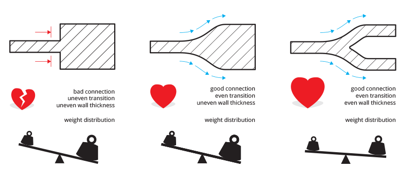
Finally, it is important to ensure that the wall thicknesses and transitions in your design are even. This rule isn’t related to the green state, but rather to the infusion of your model. Areas that have different thicknesses will heat up (expand) and cool down (contract) at different rates during and after the infusion phase. Therefore, wall thickness needs to be kept as uniform as possible to minimize the chance of cracks during this stage, and to allow a uniform bronze flow during the infusion. You can fillet or round off sharp corners in accordance with the minimum wall thickness chart to accommodate this in the best possible way. The minimum radius is 0.8mm. Connected models will not be accepted for the reasons stated above.
Holes
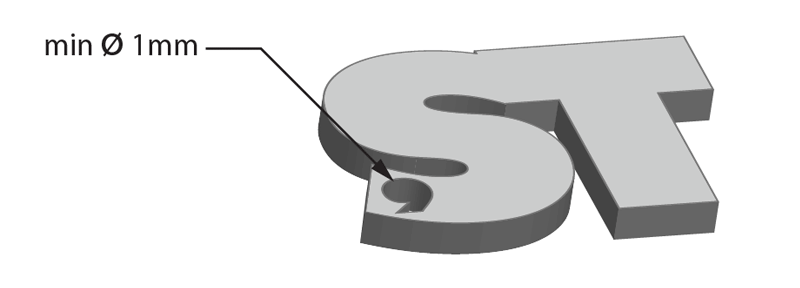
The minimum recommended diameter for a hole is 1 mm. This is the minimal diameter needed for de-powdering, without which the powder will be stuck in the geometry and get infused. Complex and direction-changing shaped holes or interior spaces are impossible for us to de-powder completely or inspect. Therefore, we cannot guarantee that these will come out consistently as designed. If perfect straight holes are required, expect that the holes in your model will be slightly smaller than designed. You can drill out the hole to match your exact measurement once the part has been built.
Wireframe Structures
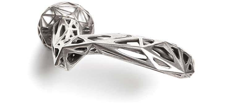
If you are interested in creating wireframe structures, please keep in mind that they are generally difficult to print. If the wires are not well supported, there is a strong possibility that your part will collapse. Do not combine large structures with thin ones. A good example of a well-designed door handle is ‘A Machine’s Perception’ by PeLiDesign, with internal beams supporting the wireframe structure.
Hollow out Your Model
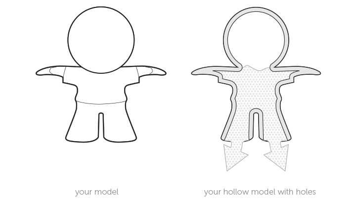
Models can be hollowed out. Try to use a minimum wall thickness of 3 mm and foresee a minimum opening of 3 mm in diameter. This opening will serve as an exit for the extra, internal powder. Larger and more complex cavities need multiple holes and an increased size. We recommend a minimum diameter of 7 mm. Holes in the center of your model are usually the best as they allow most of the powder to be removed. If any powder gets stuck inside, it will get infused. It is necessary to round the edges of the inside of your model in order to allow a good infiltration of the bronze flow.
Hollow models should be able to support their own weight. Look at the recommended wall thickness chart and add ribs to reinforce the interior of your model. This will help prevent breakage during the handling of the item in its green state.
Nested Objects, Hinged and Interlinking Parts

Nested objects (objects floating within another object), hinged parts, and interlinking parts, such as chains, cannot be made with this technique. Floating parts cannot be supported and kept separate while the object is being infused with bronze, and would, therefore, be fused together during firing.
Connection Marks
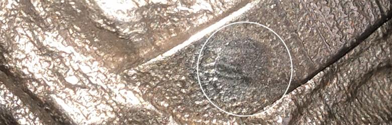
Once your part is printed, it must be infused with bronze in order to give it strength. The infusion process requires the attachment of flutes, which enable the infusion and which are manually cut off once the infusion process is complete. Flutes of 1.27 x 0.76 mm are always attached to the center of your model using a large contact area, to get an even distribution of the bronze during the infusion process. You can compare it to liquid flowing through your model at high speed. Once the flutes are cut off, any connection marks left by flutes are removed during the polishing stage. Depending on the finish, the connection mark will appear more or less prominently. If any issues are likely to arise during their removal, we will let you know beforehand.
Engraved Text and Surface Details
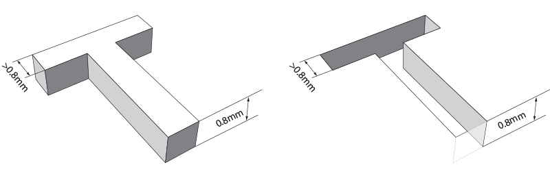
For engraved text or surface details, we recommend letters with a minimum line thickness of 0.8 mm and a depth of 0.8 mm. For embossed text or surface details, we recommend that letters have a line thickness of at least 0.8 mm and a depth of at least 0.8 mm.
Shrinkage Compensation and Dimensional Accuracy
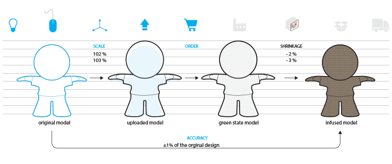
As the production of your model involves a thermal step, shrinkage is something you should take into account. We advise you to scale up the desired design by 2% for designs where X, Y or Z is below 70 mm and 3% for models which are larger. This upscale will compensate the shrinkage and as result, the dimensional accuracy will be ±1%. Dimensional accuracy does not relate to the detail of your model but to the deviation from the nominal size of your original design without the upscale. Unfortunately, we cannot guarantee this dimensional accuracy. As a result, fine mechanical applications such as threads cannot be made of this material. Small adjustments to the final printed model can be made using mechanical methods
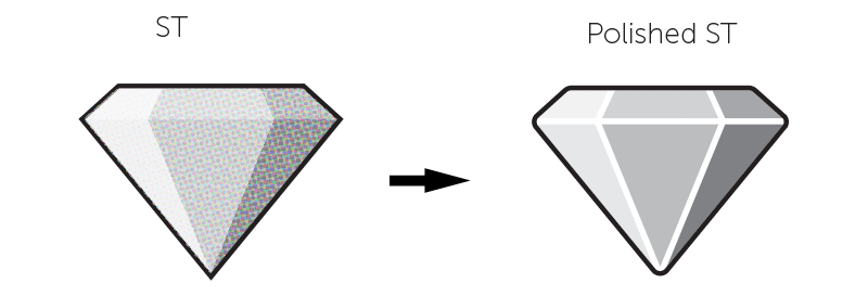
Guidelines for Polished Models
Polishing, also referred to as mechanical smoothing, is a special finishing process for Stainless Steel. To achieve a polished finish, your model is put into different tumblers with small stones that vibrate at a high frequency to smooth out the surface of your model.
Only the Strong Survive
Several factors make it hard to fully predict the outcome of the polishing process. One of these is the geometry of your model, which can act differently each time it is put in the tumbling machine. Overall, models with sharp edges will either flatten or break off in the tumbler. Polishing is not advised when your model has tiny details like pins because they will break off during the polishing process. Even though we will alert you when a polishing issue might occur, our production team can refuse to polish models if the risk of breakage is too high. In that case, you will receive an unpolished version of your model.
Rounded Edges
If your model contains sharp edges, they will be rounded off. Rounded corners and smooth transitions between surfaces will have a better polish than sharp edges.
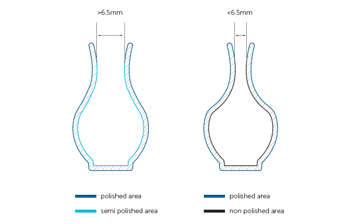
Polishing on the Inside

Small polishing stones are used to make the surface of your model smoother. Because of the size of the stones, they can easily get stuck inside small holes. Therefore, we recommend that any openings that need polishing be larger than 6.5 mm in diameter. This helps avoid the problem of stones getting stuck inside your model. Please note that the inside of your model will always be less polished than the outside – in fact, your model will not be polished at all on the inside if the holes are smaller than 6.5 mm because the stones won’t be able to enter.
Polishing stones can also easily get stuck inside V-shaped grooves. Our production team will try their best to
remove the stones but in some cases, they may not all be removed.
Color
If an area of your design is recessed or covered (e.g. an engraved area), it may become dark black in color in the final part. This happens when the area is so small that the polishing stones cannot reach inside. Also, because of the nature of the polishing process, parts higher on your model will be smoother and shinier than parts lower down.
Furthermore, if you are producing more than one piece, there can be slight variations in color between each of your pieces, even if they form part of the same production run. This is due to the infusing process, where one part may absorb more or less bronze than another.
Engraved Text and Surface Details
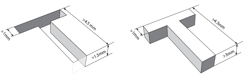
For engraved text or surface details, we recommend letters with a minimum line thickness of 1 mm and a depth of 1.5 mm. For embossed text or surface details, they need to be thick enough to withstand the impact of the polishing stones or the letters may break off. Therefore, we recommend that letters have a line thickness of at least 1 mm, an overall height of at least 4.5 mm, and a depth of at least 3 mm.
Design Specifications
- 200 x 350 x 200 mm (unpolished, unpolished black)
- 152 x 152 x 152 mm (polished, polished black, polished brown)