General Guidelines
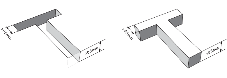
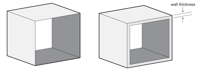
Wall Thickness
Surface Quality and Orientation
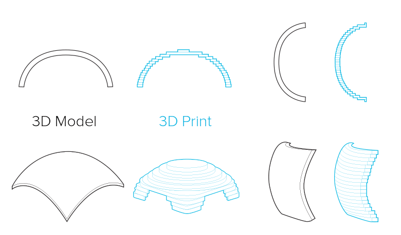
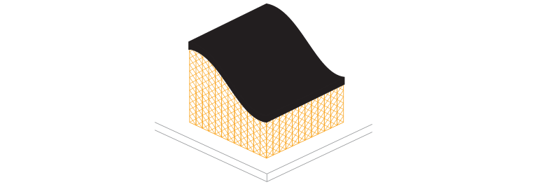
Many of the characteristics of your 3D print will depend on the Stereolithography process - the technology used to build your design in resin. Because your model will be printed layer-by-layer, the orientation will influence the surface quality and strength. On the left, you can see two examples of the same part built in two different orientations.
The horizontally-printed model clearly shows evidence of the "staircase" effect of the printing process. Its surface will be similar to that of a topographic map. If the model is printed vertically, the surface quality will be better.
Our team will select the best orientation for both the surface quality and strength of your model.
Hollow out Your Model
If possible, try to hollow out your model. In doing so you can avoid extra charges and shrinkage issues in the thicker sections. You can read about the appropriate wall strength recommendations in the section on wall thickness above.
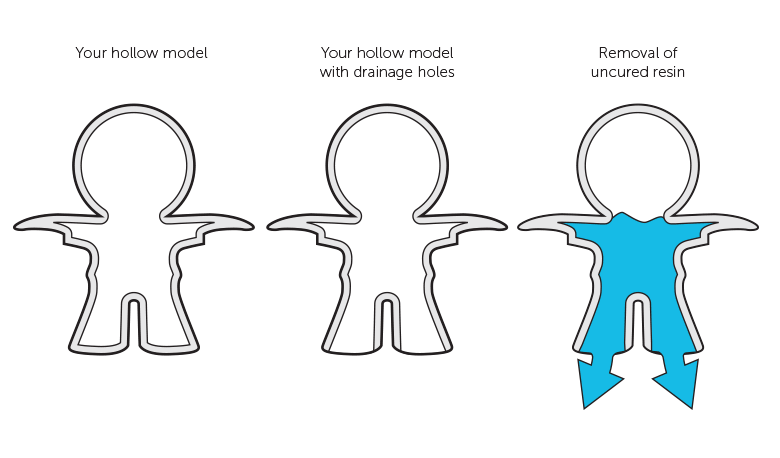
When you hollow out your model, our production team will need to integrate one or more drainage or escape holes. Usually these are placed at the lowest point(s) of your model once it has been oriented and positioned on the printer platform.
These holes keep the pressure of the liquid resin inside and outside your model at the same level. This will prevent the deformation of your design. Uneven pressure can be compared to a glass of water filled to the brim - the liquid bulges at the edges and as a result the laser scans too much material, causing your part to deform.
Secondly, the holes will be used to remove the excess resin inside the model once the printing process has been finished and your model has been removed from the 3D printer. Your model can then be emptied, cleaned and cured in a UV oven to achieve optimal strength. If the drainage holes weren’t present, the liquid resin would stay trapped.
As the position of the drainage holes depends on the orientation, our specialized production team need to decide where to place the holes. Wherever possible they will place it on a surface which is the least visible or that is easier to fill afterwards.
You can of course already include holes in your design if you want them to be in a specific location but it’s possible that our team may need to add extra holes depending on the print orientation.
Some hollow models require support material on the inside to reinforce the structure. This support structure might not be removed if we cannot access them. For more information take a look at the Internal Support section.
Support
The process of Stereolithography takes place in a tank with liquid resin. Therefore, models need to be attached to the supporting platform to prevent them from floating away. This attachment is referred to as "‘support" and is required for any model built using Stereolithography. In addition to keeping the model in place, it also enables to the construction of elements that stick out.
Rule of 30°
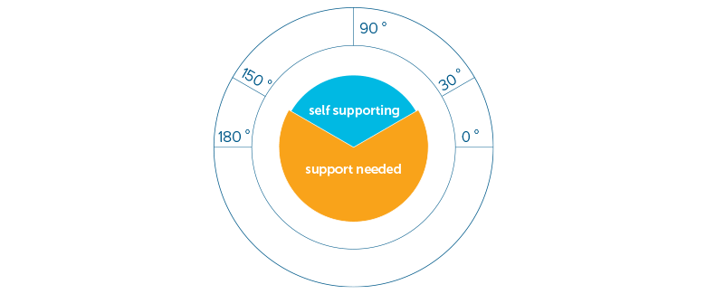
The diagram shows when a model will need support. The “self-supporting” or “safe” zone does not require any support to print the model. For most models, this area ranges from 150° to 30°. When designing an object you would like to print in resin, keep this safe zone in mind if you are concerned your model will require support to be constructed.
External Support
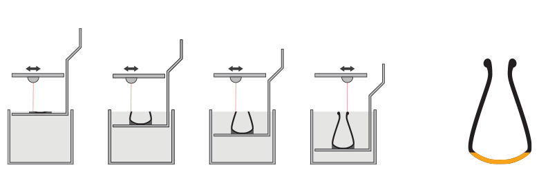
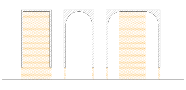
To keep your model in place and prevent it from collapsing while being printed, it needs to be supported if it has sections narrower than 30°. For example, in the figure on display, the bottom of the vase needs to be supported because it is narrower than 30°. The rest of design doesn’t need extra support because it is wider than 30°.
Internal Support
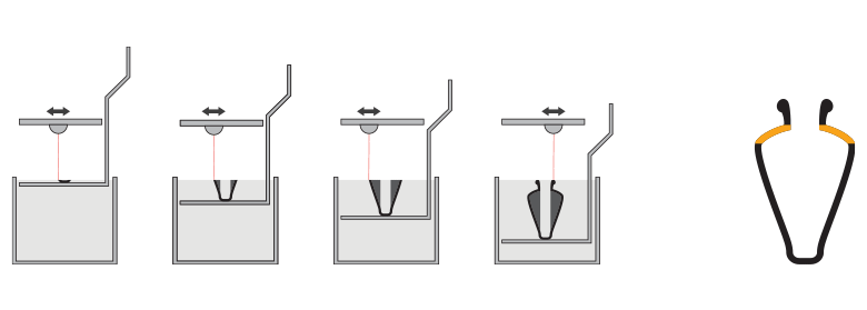
The 30° rule also applies to the inside of the model. Any model with an interior section narrower than 30° needs to be supported. For example, in the figure on display, the top part of the vase needs to be supported to prevent it from collapsing during the printing process.
As you might suspect, the removal of internal supports is far more difficult than external supports because they are usually less accessible by hand. There are usually two ways that allow the removal of internal support. The easiest option is to split your hollow design into two parts. This option will result in a design with an obvious seam or so-called split line. The other option is to include a large hole so that the inside can be accessed. This option is not possible with very complex forms, so in that case multiple holes need to be implemented. The diameter of the hole should be 10 mm or above. The larger the hole(s), the higher the chance that the internal support can be removed.
Please be aware that if the accessibility to the internal support is insufficient and can't be removed manually, some support elements may remain attached to your model or traces of support may be visible.
Avoiding Support
Engraved Text and Surface Details