General Guidelines
Wall Thickness
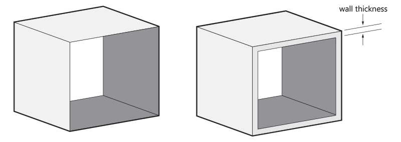
In 3D printing, wall thickness refers to the distance between one surface of your model and the opposite sheer surface. Wall thickness can either provide you with a strong solid surface, or with a flexible and expandable surface. A good example of when creating thin surface walls is ideal is when designing a spiral that needs some suspension properties. This makes your design light and flexible. The opposite effect can be achieved by making your surface walls thicker. This would be ideal for a more solid spiral-inspired flower vase.
Hollow out Your Model
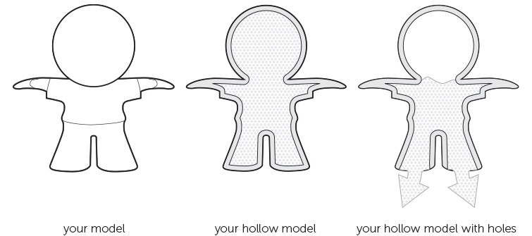
If possible, try to hollow out your model. This avoids deformation and discoloration during the printing process. You can either hollow out your model and keep the Polyamide powder trapped inside or design a strategically placed hole (two is better) so that the powder can be easily removed after printing.
Please note that our production team will hollow out models with wall that are more than 20 mm thick by default to prevent deformation and discoloration. The powder will stay trapped inside.
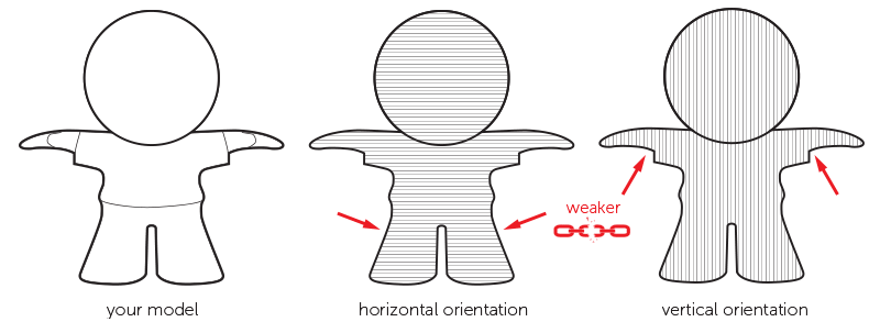
Big Flat Planes Can Cause Warping
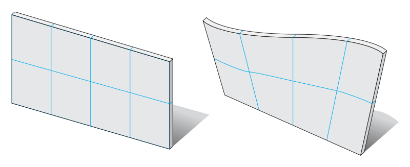
Designing a big flat plain the size of an A4 page is a bad idea. In most cases, your model will deform. This process is called "warping". Even if you create support ribs under your plane, it doesn’t solve the problem. It increases the chance of deformation even more. The key here is to avoid big flat planes.
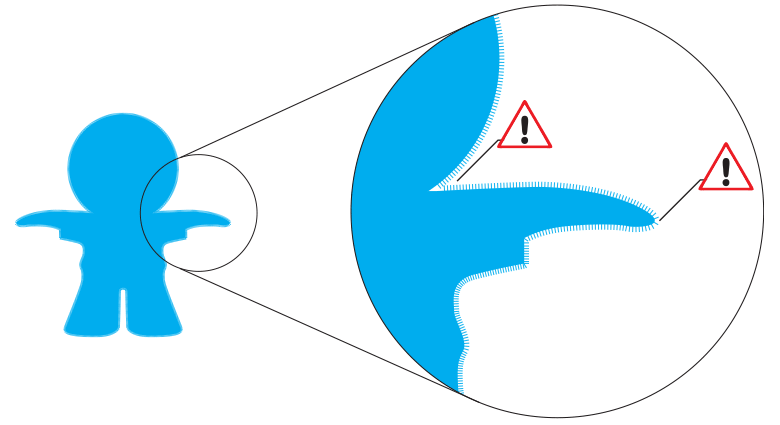
The Right Space between Your (Moving) Parts
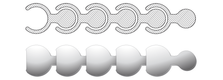
When you want to design something like a pearl or chainmail necklace, the spacing between your surfaces is crucial. It will determine the flexibility/bendability of your design. We recommend keeping a minimum space of 0.4 mm between designed surfaces. The more space you can afford the better.
The more complex your design is, the more complicated it becomes for the powder to exit the empty spaces. Try to visualize how the powder will flow through the spaces of your 3D printed design.
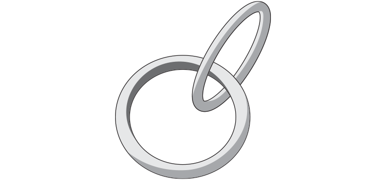
When you design something like chainmail, make sure you provide enough space between the rings in your 3D model. This will allow the powder between the rings to flow away when the model is taken out of the 3D printer.
At least 0.4 mm of space should be kept between the rings – it can always be more. The space you create between your rings will purely depend on their size. With big rings, you can create a lot of space so you can print more of them in a confined area. With small rings, you’ll have to limit your space to keep a distance between the opposite horizontal or vertical ring in the chain.
Using Surface Textures to Hide Building Layers
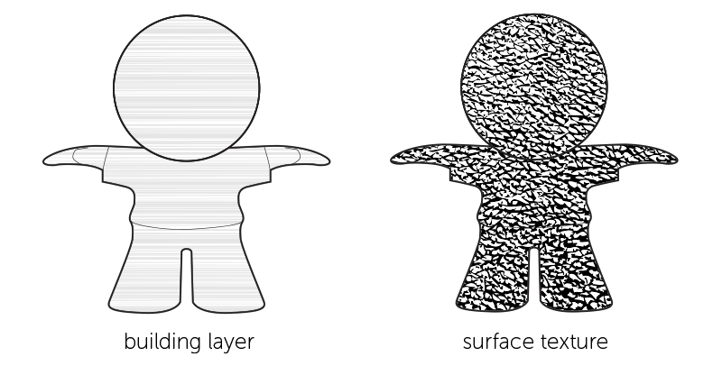
Because of the nature of the 3D printing process, a visibly layered surface often remains on your designs. To remove these visible building layers, models are often polished. However, you can also take advantage of the unsmooth surface by applying a surface texture to your model that will disguise the building layers.
Assembly
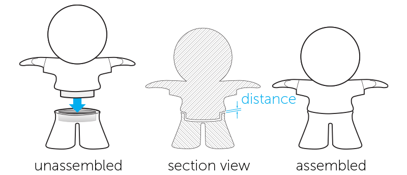
When designing models that need to be assembled, it’s important to provide enough distance between the parts that will be attached together. A perfect fit in your software package does not mean a perfect fit after printing because your software ignores the friction present in the real world. Therefore, always leave at least 0.6 mm between the different parts.
Embossed and Engraved Details
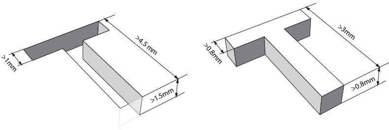
For engraved text or surface details, we recommend letters with a minimum line thickness of 1 mm, a depth of 1.5 mm, and an overall height of at least 4.5 mm. Embossed text or surface details should be thick enough that they will not break during production or transport. We recommend letters that have a line thickness of at least 0.8 mm, an overall height of at least 3 mm, and a depth of at least 0.8 mm.
Guidelines for Satin Models
The satin finish is achieved with a blasting process, giving the surface of your model a uniform color and satin smooth look.
Satin Finish on the Inside
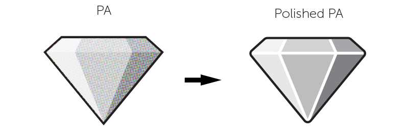
Guidelines for Polished Models
Polishing, also referred to as mechanical smoothing, is a special finishing process for Polyamide. To achieve a polished finish, your model is put into a tumbler with small stones that vibrate at a high frequency to smooth the surface of your model.
Only the Strong Survive
Several factors make it hard to fully predict the outcome of the polishing process. One of them is the geometry of your model, which can act differently each time it is put in the tumbling machine. In general, you should have wall thicknesses of at least 1 mm throughout your model. Although we carefully place and orientate your models in our printers to minimize “weak points” created by the layered buildup of your model, certain elements of your design may be more sensitive to the impacts of the polishing stones than others. Therefore, we suggest adding some extra wall thickness if your design can allow for it. Polishing is not advised when your model has tiny details like pins because they will break off during the polishing process.
Polishing on the Inside
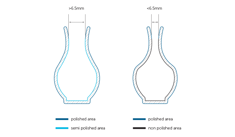
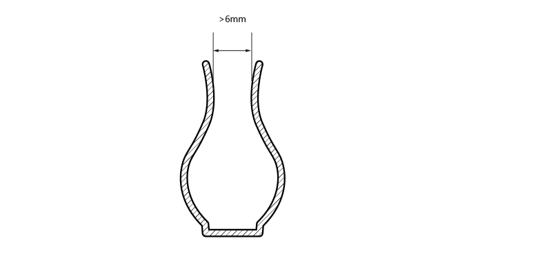
As already mentioned, small polishing stones are used to make the surface of your model smoother. However, because of the size of the stones, they can easily get stuck inside small holes. Therefore, we recommend that any openings that need polishing be larger than 6.5 mm in diameter. This helps avoid the problem of the stones getting stuck inside your model. Also, note that the inside of your model will always be less polished than the outside - in fact, your model will not be polished at all on the inside if the holes are smaller than 6.5 mm because the stones won't be able to enter.
Rounded Edges
If your model contains sharp edges, these will be rounded off. Rounded corners and smooth transitions between surfaces will have a higher degree of polishing than sharp edges. Polishing will take 0.1 mm of material off your model, so add extra wall thickness to avoid any problems.
Embossed and Engraved Details
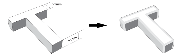
Embossed details on your model tend to be worn away by the polishing stones. Make sure to raise these details by at least 1 mm, otherwise they may disappear when your model is polished. Engraved details are less of a problem because, in most cases, the stones won’t be able to reach the inside of the engraving; however, the edges may still be affected. To be on the safe side, make sure your engravings are deeper than 1 mm.
Guidelines for Waterproof Models
For the sealing of your design, we post process your polyamide part with an aqueous solution to fill the small pores and close the outer surface or skin. Depending on the design, it is applied trough dipping or applied manually.
Accessibility
Due to the process described above, surfaces which cannot be accessed easily will most likely be treated less, leading to a lower level of sealing. For internal channels, make sure that the diameter is above 6mm or the channels could get blocked with sealing agent.
Disclaimer

Please be aware that the sealing agent improves how watertight your design is but does not guarantee a fully watertight product as this depends on several circumstances: the complexity of your design, the temperature of your surroundings, the pressure used, the liquid used etc. We recommend this finish for decorative use and advise testing your application first before fully using it.
Guidelines for Grouped Models
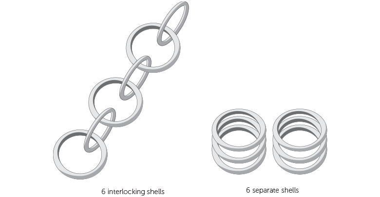
It’s possible to have several individual shells within a single 3D file. If the shells are part of interlocking elements, such as chainmail, for example, consult the rules indicated in the “The Right Space Between Your (Moving) Parts” a paragraph earlier. If the shells in your design are not interlocking or intersecting, additional design rules and considerations can be found below.
O Part, Where Art Thou?
If a single file contains several shells that are not connected or interlocking, this can cause considerable challenges for our production team. First, identification of all your parts or shells may be challenging. When producing your design, your parts are combined with parts from other orders in the 3D printer. Most printers have a fixed printing volume. To save time and costs, we fill up the machine with as many ordered parts as the build will allow. This virtual 3D layout is then used for printing. Once the printing process is finished, we end up with a block of powder with all the different parts inside. If you have uploaded multiple small, unconnected shells, you can see how it could be very difficult to go back and recognize all the different shells contained within the powder block. Therefore, to solve this issue, we only accept models that are either connected or that can be enclosed in a container or box. Continue reading below for more details and some important consequences of these options.
Connecting Parts
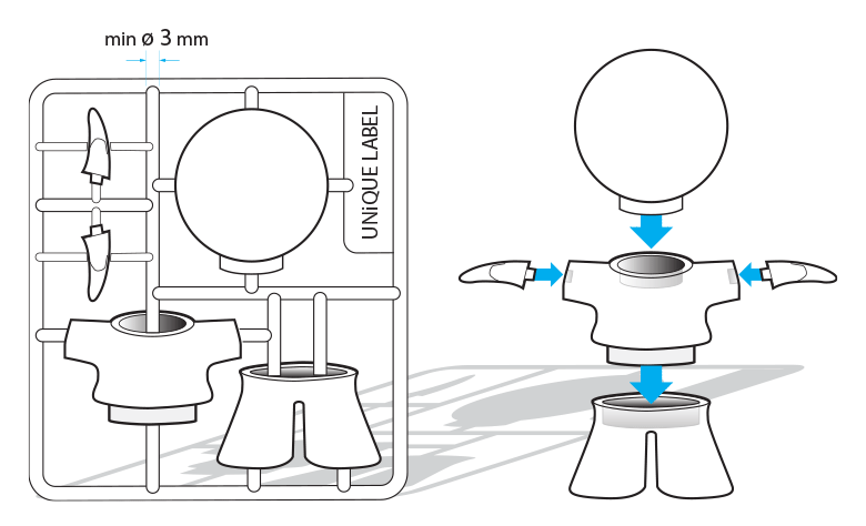
One way of making sure all the shells in your design stay together and can be processed as one part is to connect the different shells with support beams. It is important that the parts are well connected and that the connection beams are strong enough. Use a minimum wall thickness of 3 mm as anything thinner will not be strong enough to support the different parts of your design.
The heavier/bulkier your individual parts are, the thicker the connecting beams should be. If the connections between the parts are too weak, there is a risk that your parts might get lost. You can prevent bulkier shells by hollowing them out. Just don’t forget to provide several large drainage holes so that the powder on the inside can be removed – otherwise, your part will not become lighter. The part’s wall should be less than 5 mm thick.
It’s also advisable to have 4 firm connections per shell. The larger the shells, the more difficult they are to connect properly. That’s why the sum of the dimensions of the imaginary box (X+Y+Z) around your design should be less than 350 mm.
Combining Parts on a Ring
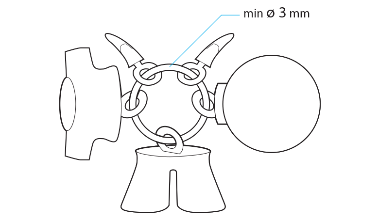
If your parts have holes through them, another way to keep them connected is by combining them on a ring. Putting your parts on a key-chain style loop ensures that we can process your designs as one part. However, when grouping your parts with this method, we can no longer orient them individually or define the correct space between them. So to avoid any problems during the build, prepare your design with a minimum of 1 mm spacing between each part. The minimum thickness of the connecting loop should be 3 mm. Make sure to limit the number of parts on the loop as too many items or large and heavy parts will have a greater chance of causing the loop to break. Designs, where the chance of breakage is too high, will not be allowed.
Grid Container
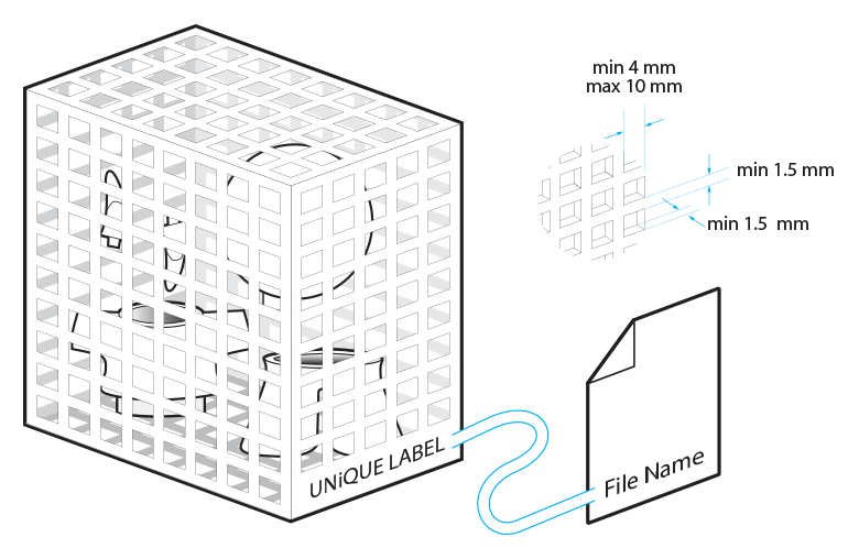
Another option that will allow you to have multiple shells printed in one go is to place all of your parts into a container. This means that you will need to design a container around you parts. Here are some basic things to take into account when designing that container. Always engrave your container with a unique label identical to the filename of your design so we can easily identify your box as we won’t be able to check the contents of your container. Use a clearly readable font such as Arial Black for the engraved text. We recommend using letters with a minimum line thickness of 1 mm, a depth of 0.8 mm, and an overall height of at least 3 mm. Additionally we ask you to add the text: "Do Not Open", on this label, to avoid that the different parts get separated.
It is advised to use a perforated container because that will allow us to remove most of the excessive powder from your parts. We recommend the following minimum feature sizes for your container: at least a 1.5 mm thickness for the grid lines; and a minimum of a 4 x 4 mm square up to a maximum of 10 x 10 mm. Make sure the parts on the inside of your container cannot pass through the perforations of the container to ensure that all your parts stay together. Parts that pass through the holes might get lost.
In addition to your container features, you also need to keep a minimum spacing distance of 3 mm between each individual part and between the sides of the container and the parts. If the distance is smaller than this, parts might get sintered together.
If the overall volume of your container is larger than 1700 cm³, you should limit the density in the container because parts that are too dense can cause an irregular cooling down process. This may cause yellowing and deformation of your parts. Limit the total volume of the model to 10% of the overall volume of the container.
If you have fragile parts in the container, we recommend connecting the individual parts to the container. This will prevent fragile parts from hitting each other during shipment. Otherwise, your parts will be loose in the closed container and may damage each other by moving around during the shipping process.
Outcomes
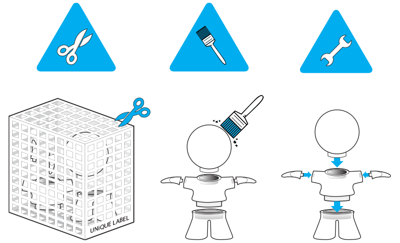
Once printed, each model will need to be cleaned with a brush and sandblasted to remove the excess powder stuck to your model. This is the same for grouped models but in these cases, access to all of the parts is more difficult. Because parts will be connected to each other as well as a container, this may prevent every edge and corner from getting sandblasted. Please be aware that some residual powder might be present when receiving your parts. To clean your parts further, the residual powder can be removed with a brush or compressed air.
Please be aware that grouped models are only offered in natural finish. Because of the limitations stated above for these types of files, a good result cannot be guaranteed. Other finishes can be achieved through various post-processing techniques but will require perfectly cleaned and fully accessible parts, which is not possible for grouped models enclosed in a container immediately upon printing.
DISCLAIMER
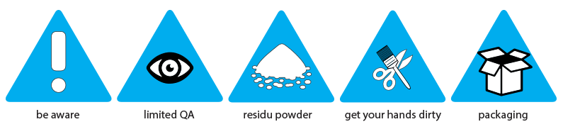
The techniques for combining multiple parts into one file that are described above will not allow us to make accurate quality inspections, to provide optimal cleaning of each part by our production team nor to pack and protect each individual part in the best way for shipment. Grouped models are only offered in natural finish. Choosing these options implies that you accept these conditions and don’t mind getting your hands dirty to do some extra cleaning of your parts.
Guidelines for Velvet Models
Go beyond painting your model and discover a special finishing option that not only changes the way the model looks but also how it feels. When adding a velvet finish to your models, a suitable adhesive is applied to the surface. Then, fabric fiber is applied that penetrates the surface of the adhesive to create the desired velvet finish.
Velvet
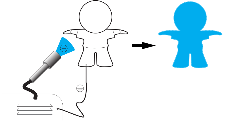
The process of adding a velvet finish to your models is called flocking and is done using an electrostatic flock applicator. First, a suitable adhesive is applied to the surface. Then a metal pin is attached to your model to ground it. With a flocking machine, the "flock" is given a negative charge so that the flock material flies vertically onto the substrate, attaching to the previously applied glue. Your model will always be marked somewhere because of the need for the ground pin to be inserted. Therefore, we recommend anticipating for a pinhole of 1.6 mm in diameter with a minimum depth of 2 mm and choosing a place where it won't be visible in your final model (e.g. bottom).
The fiber applied is about 1 mm in length. We can only add velvet fur to the A side of your models, the side that is facing outwards. It’s not possible to add velvet to the inside of your models. Velvet finish cannot be added to interlinked or moving parts
Sharp Corners and Details
Since the velvet finish is added to your original design, you’ll notice that the details of your model will appear less crisp. The adhesive will be sprayed onto the model, leaving less accessible areas with a slightly lighter coating of glue. This will cause your model to be less covered in those areas. Therefore, if choosing a velvet finish, try to avoid designing sharp corners or insides to your model (e.g. a vase). Very thin parts such as tiny details, articulated edges , or wireframes are also more difficult to cover because of limited space where the flock can attach.
Design Specifications
- 630 x 330 x 550 mm (natural)
- 630 x 330 x 550 mm (spray painted)
- 200 x 200 x 200 mm (polished)
- 270 x 150 x 150 mm (dyed)
- 400 x 400 x 330 mm (dyed black)
- 200 x 150 x 150 mm (polished and dyed)
- 200 x 150 x 150 mm (satin)
- 150 x 150 x 150 mm (velvet)
- 200 x 150 x 150 mm (priority)
- 300 x 300 x 300 mm (waterproof white)