General Guidelines
Wall Thickness
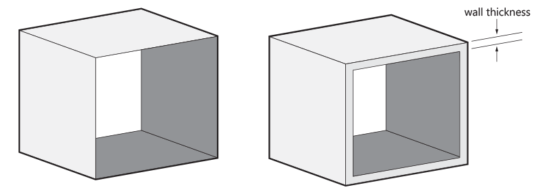
Hollow out Your Model
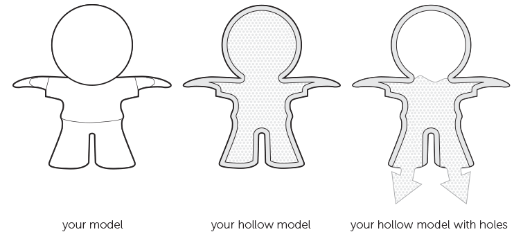
If possible, try to hollow out your model. This avoids deformation and discoloration during the printing process. You can either hollow out your model and keep the Alumide powder trapped inside or design a strategically placed hole (two is better) so that the powder can be easily removed after printing.
Please note that our production team will hollow out models with wall that are more than 20 mm thick by default to prevent deformation and discoloration. The powder will stay trapped inside.
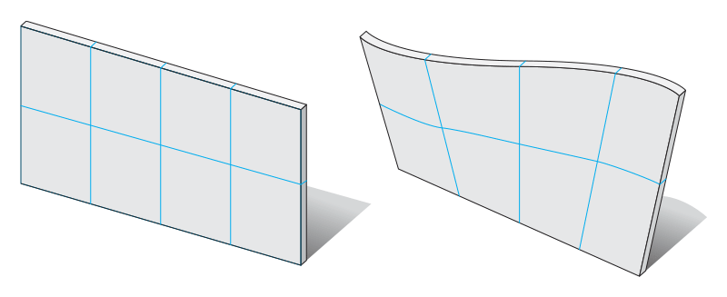
Big Flat Planes Can Cause Warping
The Right Space between Your (Moving) Parts
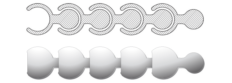
When you want to design something like a pearl or chainmail necklace, the spacing between your surfaces is crucial. It will determine the flexibility/bendability of your design. We recommend keeping a minimum space of 0.4 mm between designed surfaces. The more space you can afford the better.
The more complex your design is, the more complicated it becomes for the powder to exit the empty spaces. Try to visualize how the powder will flow through the spaces of your 3D printed design.
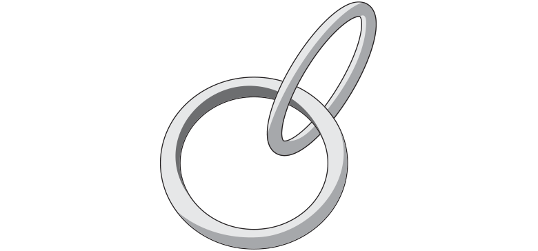
When you design something like chainmail, make sure you provide enough space between the rings in your 3D model. This will allow the powder between the rings to flow away when the model is taken out of the 3D printer.
At least 0.4 mm of space should be kept between the rings – it can always be more. The space you create between your rings will purely depend on their size. With big rings, you can create a lot of space so you can print more of them in a confined area. With small rings, you’ll have to limit your space to keep a distance between the opposite horizontal or vertical ring in the chain.
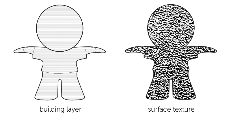
Using Surface Textures to Hide Building Layers
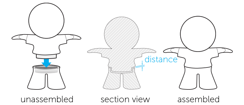
Assembly
Embossed and Engraved Details
Guidelines for Dyed Models
For dyed models, we use a dyeing process where your model is submerged into a bath containing color pigment. The dyeing process is also referred to as pigmentation or impregnating.
Visual Aspects
Guidelines for Grouped Models
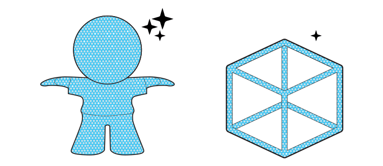
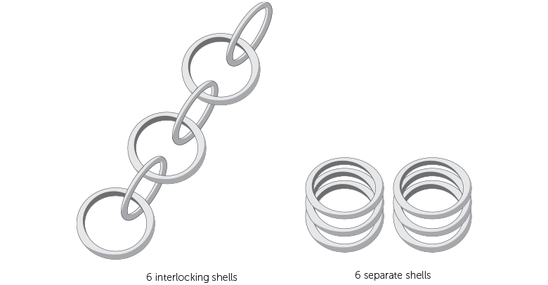
It’s possible to have several individual shells within a single 3D file. If the shells are part of interlocking elements, such as chainmail for example, consult the rules indicated in the “The Right Space Between Your (Moving) Parts” paragraph earlier. If the shells in your design are not interlocking or intersecting, additional design rules and considerations can be found below.
O Part, Where Art Thou?
Connecting Parts
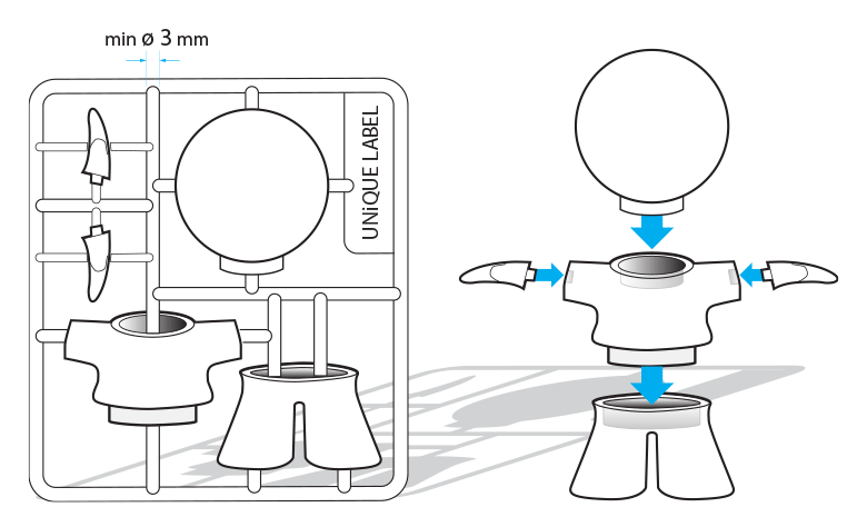
One way of making sure all the shells in your design stay together and can be processed as one part is to connect the different shells with support beams. It is important that the parts are well connected and that the connection beams are strong enough. Use a minimum wall thickness of 3 mm as anything thinner will not be strong enough to support the different parts of your design.
The heavier/bulkier your individual parts are, the thicker the connecting beams should be. If the connections between the parts are too weak, there is a risk that your parts might get lost. You can prevent bulkier shells by hollowing them out. Just don’t forget to provide several large drainage holes so that the powder on the inside can be removed – otherwise, your part will not become lighter. The part’s wall should be less than 5 mm thick.
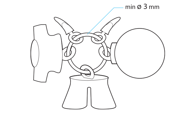
It’s also advisable to have 4 firm connections per shell. The larger the shells, the more difficult they are to connect properly. That’s why the sum of the dimensions of the imaginary box (X+Y+Z) around your design should be less than 350 mm.
Combining Parts on a Ring
Grid Container
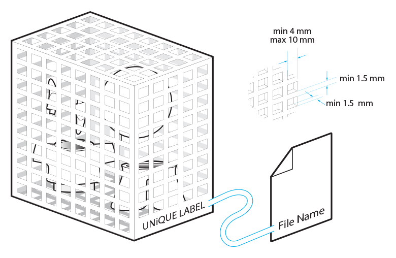
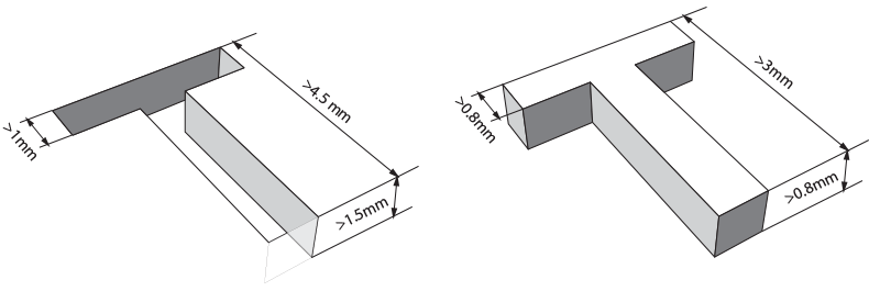
Another option that will allow you to have multiple shells printed in one go is to place all of your parts into a container. This means that you will need to design a container around your parts. Here are some basic things to take into account when designing that container. Always engrave your container with a unique label identical to the filename of your design so we can easily identify your box as we won’t be able to check the contents of your container. Use a clearly readable font such as Arial Black for the engraved text. We recommend using letters with a minimum line thickness of 1 mm, a depth of 0.8 mm, and an overall height of at least 3 mm.
It is advised to use a perforated container because that will allow us to remove most of the excessive powder from your parts. We recommend the following minimum feature sizes for your container: at least a 1.5 mm thickness for the grid lines; and a minimum of a 4 x 4 mm square up to a maximum of 10 x 10 mm. Make sure the parts on the inside of your container cannot pass through the perforations of the container to ensure that all your parts stay together. Parts that pass through the holes might get lost.
In addition to your container features, you also need to keep a minimum spacing distance of 3 mm between each individual part and between the sides of the container and the parts. If the distance is smaller than this, parts might get sintered together.
If the overall volume of your container is larger than 1700 cm³, you should limit the density in the container because parts that are too dense can cause an irregular cooling down process. This may cause yellowing and deformation of your parts. Limit the total volume of the model to 10% of the overall volume of the container.
If you have fragile parts in the container, we recommend connecting the individual parts to the container. This will prevent fragile parts from hitting each other during shipment. Otherwise, your parts will be loose in the closed container and may damage each other by moving around during the shipping process.
Outcomes
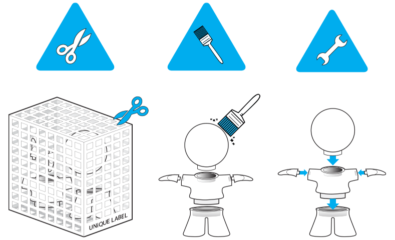
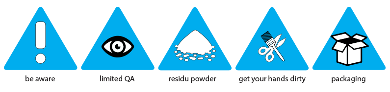
Once printed, each model will need to be cleaned with a brush and sandblasted to remove the excess powder stuck to your model. This is the same for grouped models but in these cases, access to all of the parts is more difficult. Because parts will be connected to each other as well as a container, this may prevent every edge and corner from getting sandblasted. Please be aware that some residual powder might be present when receiving your parts. To clean your parts further, the residual powder can be removed with a brush or compressed air.
Please be aware that grouped models are only offered in natural finish. Because of the limitations stated above for these types of files, a good result cannot be guaranteed. Other finishes can be achieved through various post-processing techniques but will require perfectly cleaned and fully accessible parts, which is not possible for grouped models enclosed in a container immediately upon printing.
DISCLAIMER
Design Specifications
- 630 x 330 x 550 mm (natural)
- 270 x 150 x 150 mm (dyed)