Wall Thickness
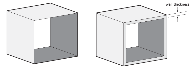
In 3D Printing, wall thickness refers to the distance between one surface of your model and the opposite sheer surface. For ABS, we recommend a minimum wall thickness of 1.2 mm.
Surface Quality and Orientation
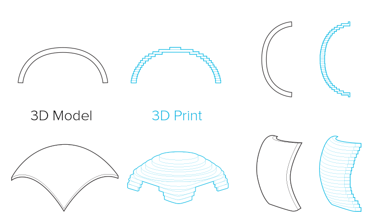
Many of the characteristics of your 3D print will depend on the Fused Deposition Modeling process – the technology used to build your design in ABS. Because your model will be printed layer by layer, the printing orientation will influence the surface quality and strength. On the left, you can see two parts of the same shape but built with different orientations.
The horizontally printed model clearly shows the “staircase” effect of the printing process. Its surface will be similar to that of a topographic map. If the model is printed vertically, the surface quality will be better.
Think about which surface needs to have the best finish and choose the orientation accordingly when printing.
Anisotropy
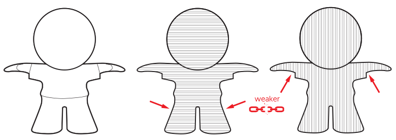
Because your model is built up layer by layer, it will always have “weak points” caused by its printing orientation. These weak points can cause thin external elements of your design to easily break off. Therefore, avoid features on your model that are parallel to the base or bottom plane and that will require strength to support them.
Dimensional Accuracy
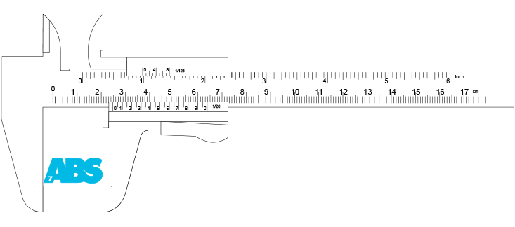
Fused Deposition Modeling is one of the plastic 3D printing processes with the highest dimensional accuracy. Dimensional accuracy doesn’t relate to the detail of your model but to the deviation from the nominal size. The general tolerance of the material we offer is 0.1% with a minimum of ± 200µ.
Support
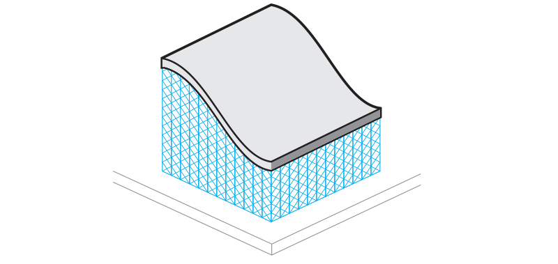
Fused Deposition Modeling takes place on a building platform. Since models will be “built in the air”, they must be attached to the supporting platform to prevent them from collapsing. This attachment is referred to as the “support” and is required for any model built using this technology. In addition to keeping the model in place, it also enables the construction of elements that stick out. After the building process is complete, the support is manually removed. Please note that your model may display visible evidence of the removed support structures.
Base
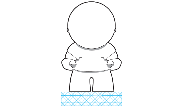
In order to build your parts, they must be designed with a base on which to attach the support structure. With this in mind, you should take into account that the bottom surface will be rougher than the rest of your model.
External Support
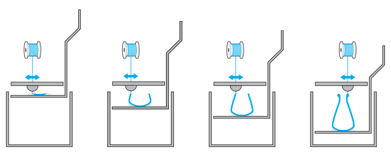
To keep your model in place and prevent it from collapsing while being printed, models that have sections narrower than 45° must be supported. In the example on the left, the bottom of the vase must be supported because it’s narrower than 45°. The rest of the design doesn’t require extra support because it is wider than a 45° angle.
Internal Support
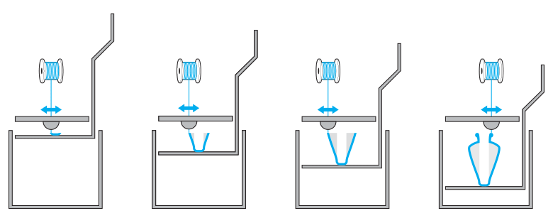
The 45° rule also applies to the interior of your model. Any model with an interior section below 45° must be supported. In the example on the left, the model on top must be supported to prevent it from collapsing during the printing process.
Rule of 45°
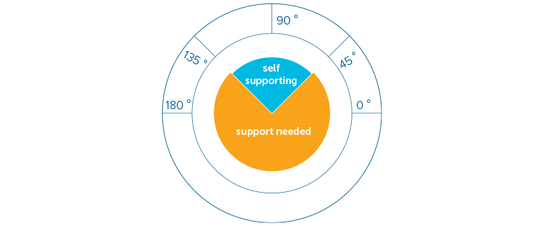
The diagram on the left shows you when a model requires support. The “self-supporting” or “safe” zone does not require any support to print the model. For most models, this area ranges from 135° to 45°. When designing an object you would like to print in ABS, keep this safe zone in mind if you are concerned your model will require support to be constructed.
The Right Space between Your (Moving) Parts
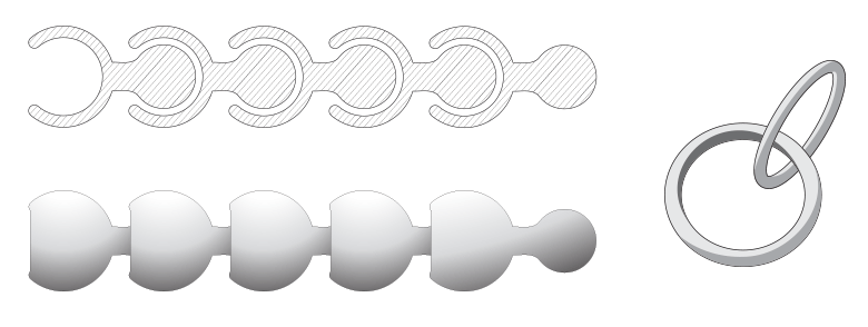
When you want to design something like a pearl or chainmail necklace, the spacing between your surfaces is crucial. Spacing will determine the flexibility/bendability of your design. We advise you to keep a minimum space of 0.4 mm between designed surfaces. The more space you can afford the better.
In the example of a necklace, the space you create between your rings will purely depend on their size. With big rings, you can create a lot of space so you can print more of them in a confined area. With small rings, you will have to limit your space to keep a distance between the opposite horizontal or vertical ring in the chain.
Assembly
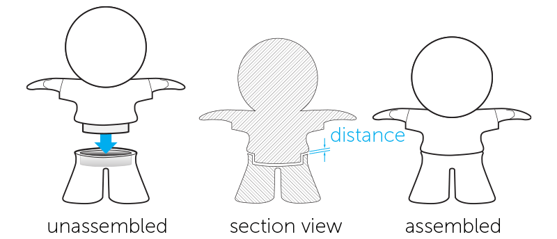
When designing models that need to be assembled, it’s important to provide enough distance between the parts that will be attached together. A perfect fit in your software package does not mean a perfect fit after printing because your software ignores the friction present in the real world. Therefore, always leave at least 0.3 mm between the different parts.
Embossed and Engraved Details
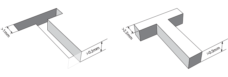
In general, engraved text or details are preferable to embossed text or details. For engraved text or surface details, we recommend letters with a minimum line thickness of 1 mm and a depth of 0.3 mm. For embossed text and surface details, we recommend letters that have a line thickness of at least 2.5 mm and a depth of at least 0.5 mm.


